Have you ever wondered what the exact angles your wrist, fingers, elbows, and shoulder need to form to pick up a glass of water optimally? Yeah, me neither - your brain just knows what to do, it's automatic. A lot of that is from years of experience and instinct, but you are also getting visual feedback from your eyes and tactile feedback from your hands. For a robot, which lacks both human instinct and senses, every movement needs to be carefully planned out.
Kinematics is the branch of physics regarding the motion of objects, which we use to define how parts of a robot move in relation to one another. It's math that tells a robot, "if you want to get over there, move yourself like this."

A glass of water sitting on a table - the fearsome adversary of any robot arm
Forward Kinematics: From Joints to Position
Let's pretend we live in a dystopian cyberpunk future complete with neon lights, sketchy alleway mechanics, and of course a horrific factory accident that costs you an arm. Unfortunately since money's tight and universal healthcare still doesn't exist you ended up with a pretty simple robot prosthetic replacement arm. No wrist rotation or fingers - just a budget friendly claw that can open and close.
Still with me? Now how would we program that arm to pick up pesky cups of water sitting on tables?
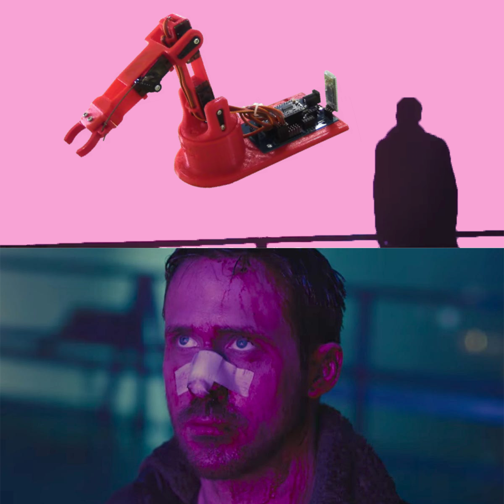
Your new arm that'll get you back in the factory in no time
Forward kinematics is the process of calculating where a robot's tool will be given the angles of its moving parts and the size of the robot. It's used to calculate the exact position of your "hand" based on the angles of the two moving parts and the lengths of the two arm segments, perfect for planning precise movements like grabbing pesky cups of water sitting on tables.
To start programming our prosthetic, we need to define a few things. A joint is where two links of the robot come together and rotate. If your arm were a robot arm, your shoulder and elbow would be considered joints. These are usually depicted as circles in kinematic diagrams and drawings. Links are the solid segments between joints — in your arm, your forearm and upper arm are the links. These are depicted as lines between circles (joints) in diagrams. The end-effector is the tool attached to the end of the robot. For you, that's the gripper I mentioned. For other robots, this could be a suction cup, welding tool, or some other device — the whole point of a robot arm is usually to move a specialized tool to the right spot to complete a task. Usually, end-effectors are depicted as another joint at the end of the last link, or are ommitted from diagrams altogether (since end effectors vary from robot to robot, we only really care about where they end up in space).
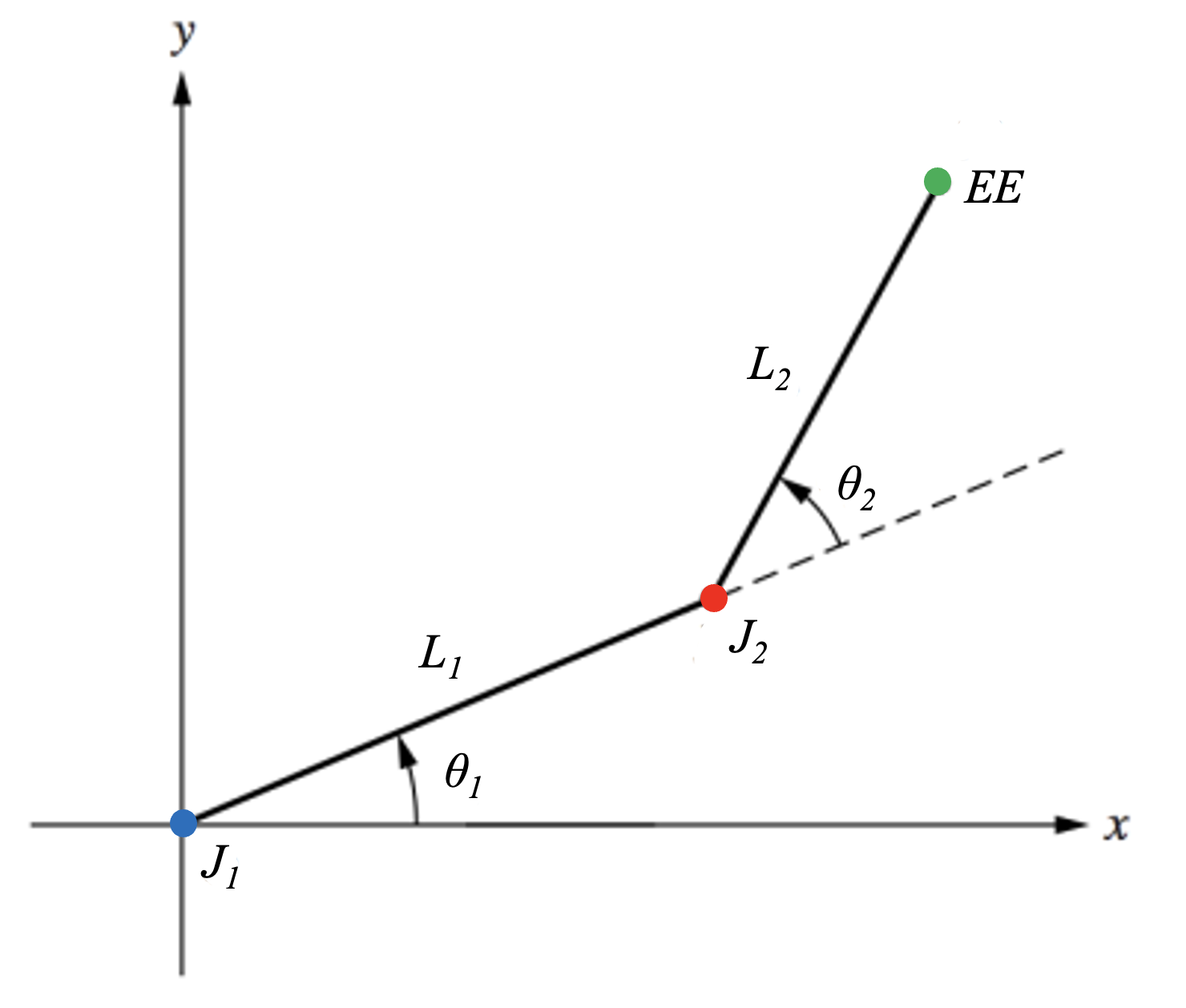
Now that we know what the parts of the robot are, take a look at the diagram above. This is a kinematic diagram of the robot arm I described earlier. Starting from the origin, we can trace the arm's structure: the blue dot J₁ represents the first joint (basically where your shoulder would be), followed by L1, which is the first link of the arm (your upper arm). The second joint, J₂, represents your elbow, and L2 is your forearm. Finally, the end-effector (EE) represents the gripper at the end of the arm.
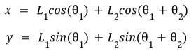
We can predict exactly where that end-effector will end up by treating each link as a vector and using some trigonometry to find the position of the end-effector. The equations to calculate the (X,Y) coordinates of our end-effector are:
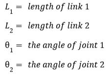
where
The first parts of the equations, L₁cos(θ₁) and L₁sin(θ₁) are pretty straightforward - they calculate the position of the end of Link 1. However since Link 2 is attached to the end of Link 1, we need to add both angles in the second part of the equation (L₂cos(θ₁+θ₂) and L₂sin(θ₁+θ₂)) to compensate for Link 1's position. If we had more than 2 links, we'd continue this pattern of adding the angles of the previous links to the current link's position.
Try It Yourself!
Here's an interactive tool where you can experiment with forward kinematics on a 2-link robot arm. Try adjusting the link lengths and joint angles to see how the robot moves!
Link Lengths
Joint Angles
Current Position:
X: 0, Y: 0
θ₁: 45°, θ₂: 45°
The (annnoying) Problem of Multiple Solutions
One tricky thing about kinematics is that there are often multiple valid combinations of joint angles that can get you to the same place. For instance, if you were reaching for a cup of water you could bend your elbow in two different ways (one normal, one awkward) and still get your hand to the cup. And what get's even trickier is that in some instances you have to maneuver around obstacles, which means you have to find the best solution out of many possible ones.
Inverse kinematics is like reverse-engineering a robot's movements. Instead of plugging in the angles like we did in the forward kinematics section, we're going to plug in the desired position of the end-effector and solve for the angles. This is a lot more useful than forward kinematics (even though it's a lot more complicated) because now we can think of a place we want to move the robot and solve for the angles that fit that solution.
The inverse kinematics equations for the same 2-link robot arm are:
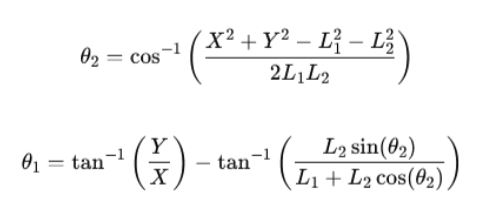
We skipped over some of the derivation of these equations here because it's pretty complicated, and since no two robots are exactly the same, the process for finding these equations is different for each robot. (but we will cover it in a future lesson). Instead, try out this tool below - set your robot's link lengths and then click anywhere on the grid to see the required joint angles to move the end-effector to that point (and while you're at it, check out the alternate solution to see another possible solution)
Link Lengths
Target Position
Solution:
θ₁: 45°, θ₂: 45°