We’ve mapped out a robot’s muscles, eyes, and a bit of the brain, so let’s get into how these parts communicate with one another. Electronics, unsurprisingly, communicate with signals made of electricity. These signals are voltages going up or down and come in one of two “languages.”
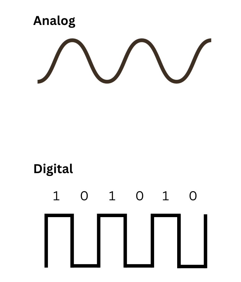
The first is digital, which consists of clean on & off steps, like speaking in Morse code. The other is analog, a continuous signal that can vary in many ways. It's more akin to whistling to someone, as you can slide up or down in pitch and carry a unique message based on the sound at that exact moment.
Most sensors use analog to take measurements of fine, continuous details of the real world. For instance, if you needed to measure temperature you might use an analog sensor called a thermocouple, which produces a voltage that scales directly with temperature. That voltage can then be translated into Celsius, Fahrenheit, or Kelvin.
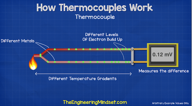
Thermocouples don't really have much to do with the rest of this lesson, but the way they work is pretty cool!
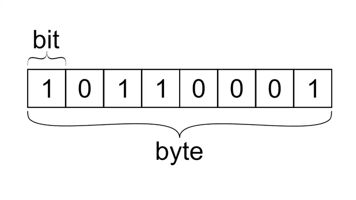
Computer processors only “speak” digital, so every signal in a system eventually gets chopped into digital data. The smallest unit is a bit — just a 0 or a 1. Group eight bits together and you get a byte, which is the basic “chunk” most systems care about at once. On the wire, these aren’t abstract numbers — they’re real voltages flipping high and low, like Morse code firing off at light speed.
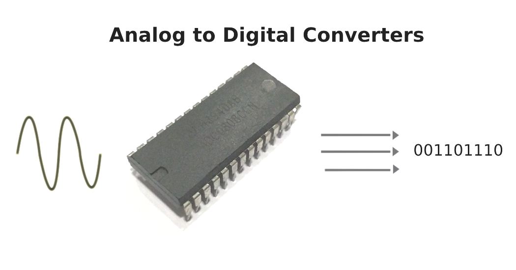
So since robots use both analog and digital, we need ways to translate from one to another. That’s where ADCs (Analog-to-Digital) and DACs (Digital-to-Analog) come in.
ADC Visualizer: Converting Analog → Digital
What's happening here?
An ADC (Analog-to-Digital Converter) takes a smooth, continuous analog signal and chops it into snapshots that a computer can understand as digital numbers. The sampling rate is how often those snapshots are taken.
At low sampling rates, the digital version looks choppy and can even misrepresent the original signal (aliasing). At high sampling rates, the digital signal starts to closely match the analog one. That’s why the sampling rate is important for things like audio, video, and robot sensors!
What is it literally?
It's not actually a graph, but a real circuit made of transistorsA tiny electronic switch that can turn current on or off (or amplify it), and is the basic building block of modern circuits. and capacitorsAn electrical "storage tank" that temporarily holds and releases energy, like a tiny rechargeable bucket!, usually packaged as a tiny chip. Sometimes it's a standalone part you wire up, other times it's built directly into your robot's microcontroller so you don't even see it. Either way, its whole job is to sit between the analog world (smooth voltages from sensors) and the digital world (numbers your robot's brain can process) and act as the translator.
DAC Visualizer: Converting Digital → Analog
What's happening here?
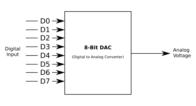
A DAC (Digital-to-Analog Converter) does the opposite of an ADC - it takes digital numbers and reconstructs them into a smooth, continuous analog signal. The reconstruction type determines how smooth that output becomes.
Basic reconstruction gives you blocky, step-like output that's simple but can sound harsh. Filtered reconstruction smooths out those steps to create natural-sounding curves. This is how your digital music gets converted back into the smooth sound waves that come out of your speakers!
What is it literally?
A DAC is also usually a tiny chip made of transistors, capacitors, and resistor ladders.A network of resistors (things that measure resistance) arranged like the rungs of a ladder that divides voltage into precise steps, often used inside DACs to turn digital numbers into proportional voltages. Like an ADC, it might be a standalone component you wire up or built directly into your robot's microcontroller. Inside, these parts work together to take digital numbers and "smooth" them back into real-world voltages, converting binary steps to a continuous signal.
The Life of a Signal
Bits and bytes make up the 'alphabet', and analog/digital are 'languages'. But signals need structure and rules so that it don’t turn into a cacophony of random noise. That’s where buses and communication protocols come in.
A data bus is simply the pathway that signals travel along, like a shared road that makes sure information gets where it needs to go. Buses transfer bytes (remember, a byte is 8 bits, so 8 digits consisting of 0’s and 1’s) one of two ways. Parallel communication is transfers each bit over 8 separate wires. Serial communication sends each bit sequentially over a single wire. Most systems almost always use serial communication since it’s simpler, more reliable, and saves valuable wire space in larger systems.
Let’s combine all of that info to map out the life of a signal inside of a robot - from sensor reading to actuator movement.